ACA Dynamic Background Patch: the Inside Story
Tom Aldcroft, Mark Baski, Jean Connelly, Paul Viens
A tense moment
Chandra Operations Control Center (OCC), Burlington, MA—It's 8:44 PM EDT on May 18, 2023, and the moment of reckoning is upon us. We are about to send the commands to activate a patch that fundamentally alters the operation of the Aspect Camera Assembly (ACA), a critical sensor for keeping Chandra oriented in space and safe. There are 11 people from the Chandra X-ray Center (CXC) flight and science operations teams in the room, with dozens more from the CXC and NASA following along online. If successful, the patch will dramatically improve the ability of the ACA to track guide stars and claw back flexibility for Chandra science observations in the face of ever-mounting thermal constraints.
This moment is the culmination of years of development, analysis, testing, review, and rehearsals. Ironically, the immediate desired result is almost imperceptible. From thousands of telemetry data points we receive from Chandra, there is just a single status flag—AABGDTYP from the ACA—that should change from ORIG to DYNB. What we do not want to see is evidence for any of the worst-case scenarios that we considered and rehearsed, such as an autonomous reset of the ACA electronics, which would force a Chandra safing action to use the Sun for attitude control and interrupt the science mission for a day or two.
The operations controller (OC) announces on the voice loops that we are at step 21 of the uplink Command Action Procedure to run script A_PEA_PATCH_ACTIVATE to activate the patch. After a final check of telemetry and an internal poll on the voice loops, the PCAD engineer gives the go-ahead to OC and the commands are sent to Chandra via the JPL Deep Space Network (DSN). A few seconds later, exactly as expected, AABGDTYP changes to DYNB. That’s a huge milestone, but the next minute or two are critical. Will Chandra remain stable and locked solidly on the eight guide stars? The seconds tick by, and, with mounting relief, we see that nothing unusual is happening. Chandra is quietly executing its dither pattern in Normal Pointing Mode, just like it has for the previous 24 years.
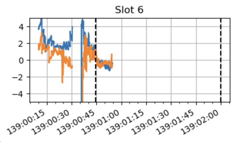
The team can start breathing again, but we still need to wait about 10 minutes to see that it is actually improving tracking. Below we see part of the actual diagnostic plot that was posted to the team internal Slack channel at 8:55 PM. The first vertical dashed black line is the time of patch activation around 8:44 PM (00:44 GMT) and the second dashed black line is the expected end of track during the DSN communication pass. The blue and orange traces represent the star centroiding error (arcsec) in each axis for star 6. Later in the article we’ll talk about what causes that error, but back in the OCC Control Room what matters is that the patch is functionally working and reducing the centroiding errors from over 4 arcsec to under 1 arcsec. Another milestone!
After a few more checkout activities and another hour watching the patch behave perfectly, we can finally declare an unqualified success. A bottle of non-alcoholic sparkling wine appears, and the cork is popped to celebrate a major milestone toward the next chapter of Chandra science!
What brought us to needing this ACA patch?
Hot hot hot!
The plot below shows the first and most important part of the answer. Every Chandra observer knows that the spacecraft is getting warm. But you may not realize just how hot parts of Chandra have become! The Fine Sun Sensor (FSS) is located on the Sun-facing side of the spacecraft and is exposed to the full brunt of the Sun’s intense radiation, with peak temperatures regularly exceeding 230 °F (110 °C). With the continuing degradation of the protective silverized teflon multilayer insulation (MLI) due to the radiation environment, the FSS temperatures have been climbing linearly for close to 20 years. Earlier in the mission we imagined that at some point Chandra would effectively become a black body and that this curve would flatten. This optimism has been replaced by acceptance that the linear trend will likely continue for as long as Chandra operates, and we must plan accordingly.
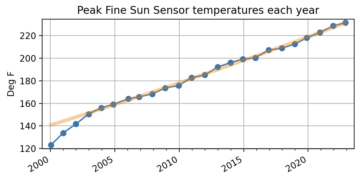
We hope this plot will also give you a better appreciation for the effort of the CXC as a whole to successfully manage Chandra operations to continue providing a platform for cutting edge X-ray astronomy. The excellent engineering of the spacecraft and instruments has given us the opportunity, but it is the ingenuity and dogged persistence of the CXC that keeps Chandra going day after day.
A bit about the ACA
The next part of the story requires a short detour to talk about the ACA itself. The ACA consists of the aspect camera (the optics and CCDs) and the Processing Electronics Assembly (PEA), which controls the camera and interfaces with other Chandra electronics. The aspect camera is an 11.2 cm diameter F/9 Ritchey–Chretien optical telescope that sits deep in the spacecraft just outside the High Resolution Mirror Assembly (the X-ray mirrors). It is co-aligned with the telescope and has a field of view of about 1.4° x 1.4°. Broadly speaking, the ACA is designed to track stars in the 6th to 10th V magnitude range.
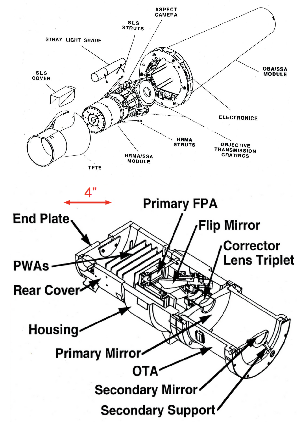
The aspect camera focal-plane detector is a 1024×1024 Tektronix CCD chip with 24 micron x 24 micron (effectively 5 arcsec x 5 arcsec) pixels, covering the spectral band between 4000 and 9000 Å. The optics of the camera are defocused to spread the star images over several CCD pixels to increase accuracy of the centroiding algorithm. There is a spare identical CCD chip, which can be illuminated by inserting a rotatable mirror.
The ACA electronics track a small 8 pixel x 8 pixel region around each star image or fiducial light (used for measuring alignment to the science instruments). There are a total of eight such tracking image slots. During most science observations, five guide stars and three fiducial lights are tracked. The PEA does image processing to subtract an estimated background and compute image centroids with a first-moment centroid. The image centroids and magnitudes are used by Pointing Control and Aspect Determination (PCAD) flight software within the On-Board Computer (OBC) and are also telemetered to the ground along with the raw pixel data.
Dark current
In order to get the best photometry, observers understand that an important step is to remove instrumental effects; for the ACA, this starts with the intrinsic dark current of the CCD, which generates a background signal during the integration. Dark current measurement is commonly done by doing an integration with the camera shutter closed, but there is no shutter in the aspect camera. Every 2.05 seconds the PEA issues a command to the camera to flush the CCD, after which the CCD then performs a 1.7 second integration followed by a readout of the active image slot pixels. The original design of the ACA processing computes a flat background level for each image using 8 corner pixels of the 8×8 readout, with a simple (but not always effective) sigma-clipping algorithm to reject outliers in the background pixels.
The ACA does support a special calibration mode where it can perform a full-frame readout (including sky background and stars which are removed post-facto). This is regularly done to maintain a map of the dark current and trend the CCD health. However, the ACA is unable to store and use this ground dark current image directly given that the PEA has only 64K of RAM.
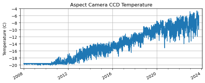
The original design requirements accounted for potential "dark-current non-uniformity" based on estimates of five years of ionizing radiation damage to the CCD and under the assumption that an integrated Thermo-Electric Cooler (TEC) would be maintaining thermal control of the CCD temperature. Those requirements did not anticipate that Chandra would still be going strong well into its third decade (meaning five times more radiation damage), and that the external thermal environment would eventually overpower the TEC and cause loss of CCD temperature thermal control. The dark current in the TK1024 CCD roughly doubles with each 8 °C increase in temperature, and since 2010 the CCD temperature has increased up to 16 °C—a factor of 4 penalty on top of the factor of 5 in radiation damage.
Impact on science capability
The practical impact of dark current can be seen below, where we show two simulated CCD images of a 10.5 mag star: one under conditions from 2010, with the CCD thermally controlled at −20 °C, and the other from 2023, with the CCD lifted off of thermal control at −5 °C. The white box denotes the 8×8 readout window. Both images have the same color scaling. The 2023 image is essentially lost in the dark current noise. Making matters worse is the hot pixel on the lower right side that would dominate the first moment centroid calculation.
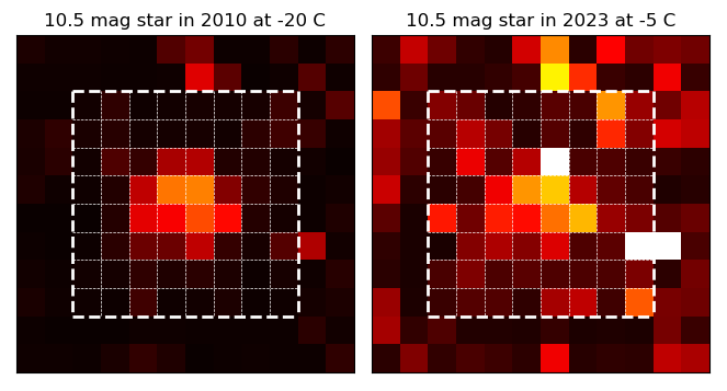
In order to maintain spacecraft safety, we require that guide stars be bright enough to maintain the star signal-to-noise above a threshold. This brings us to the crux of the matter: at CCD temperatures above −10 °C there start to be areas of the sky where there are simply not enough bright stars in the ACA field of view to safely perform an observation. At −5 °C this area is large enough that a substantial fraction of observations are not allowed, leading to constraints to perform the observation with the ACA CCD colder. This requires special handling by the mission planning teams and increases complexity and effort.
This constraint has led to the creation of the Star Field Checker web tool to allow proposers to check that their target can be observed within the planning guidelines. Without the dynamic background PEA patch, some proposers in the next cycle would be getting the unfortunate news that their science target is not feasible even with special handling. Instead, with the margin provided by the patch, this circumstance is still quite rare at this time.
A proposal in 2017
Jumping back in time to 2017, the problems of increasing dark current and CCD temperature and the expected impact to science were well-understood. In September of that year a community-wide briefing was held with a focus on current performance and predictions for the next 5 years. Leading up to that meeting we had technical internal discussions to brainstorm ideas big and small to mitigate the predicted science impacts.
An idea that gained traction takes advantage of the fact that nearly all Chandra observations are done with a pointing dither pattern. Instead of staring straight at the target, Chandra normally rocks gently about in a Lissajous pattern with a 16 arcsec box size. Since the pixels near the edge of the 8×8 readout window are largely unaffected by light from the star, they provide an on-board measurement of the dark current and zodiacal light background. As long as Chandra dithers and the readout window follows this pattern, the PEA could dynamically assemble a background map to subtract from the raw image data prior to centroiding. In order to prevent transients like cosmic-ray hits from corrupting the background, the algorithm would maintain a history of five readouts and do a median filter.
The idea was christened with the name "dynamic background," and we quickly added code to our software ACA simulator to see if it would fly. The initial results we presented to the community briefing were impressive and dramatic. March of 2017 had been a terrible time for ACA, with three major anomalies in a single month from failing to acquire stars at the end of a maneuver. With this still burning in our memories, we choose the Bright Star Hold (BSH) on March 30 to bring home the point that with dynamic background subtraction that anomaly would never have happened! The reason for the March 30 BSH was that a hot pixel on the CCD infiltrated the star image and induced a huge perturbation in the centroid, which in turn caused a large error in the on-board estimated roll. With a bad starting attitude the subsequent maneuver landed far away from the intended target and the ACA failed to find the expected stars. Instead, with dynamic background in place, the centroids track the sinusoidal spacecraft dither pattern perfectly and the error in estimated roll (offset) is small.
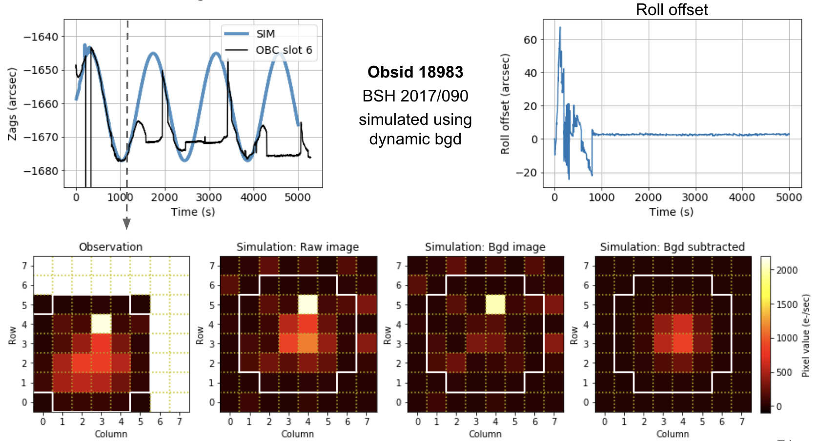
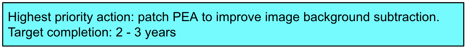
During the meeting there was a comment that 2–3 years seems like a very long time, and we pointed out that the patch was going to be a bit complicated to develop so we were including some margin. The astute reader will now note that it actually took nearly 6 years to develop and uplink. So what happened? In the next section we will dive into the "it’s complicated" part. But this is a good time to talk about the reality of running a mission like Chandra. We have already seen that nominal mission operations are complicated and require both deep attention and continuing innovation. Indeed, during that time we made several key improvements, including a major effort to improve the star selection process and a patch to the on-board computer to reduce sensitivity to ACA hot pixels. But Chandra is also a very complex and aging spacecraft, and the consequences of that are very real in the form of anomalies that require very significant resources. During those 6 years Chandra experienced enough major anomalies to repeatedly divert attention from our "highest priority" action, sometimes for months at a time. But at the end of the day, better late than never!
It’s complicated
The reality of the ACA is much more complicated than the initial proof of concept simulations. The ACA operates in a hostile environment and is subject to instrumental effects that could render the new algorithm ineffective. We needed to devote substantial resources to prove unequivocally that it would work.
We already mentioned cosmic ray hits that can sometimes obliterate a readout. However, a more pernicious problem is that the cosmic ray hit can perturb the centroid enough to fool the PEA into moving the tracking window several pixels, erroneously believing the star has suddenly started moving quickly. This will then put the star light into the edge pixels and start corrupting the background map. Another issue is that damaged pixels on the CCD are subject to unpredictable fluctuations in intensity, where the intensity will suddenly change by up to a factor of two after having been steady for several hours. This so-called flickering means that the background itself is a moving target. A final challenge—and by far the most impacting to the algorithm—is that about a few dozen times a year the ACA will experience a transient high-background anomaly. In this situation the apparent background of several or all image readout slots will rise dramatically for a period of up to a few hundred seconds. In many cases the background entirely saturates the image and the star is not tracked. In simulations we demonstrated that under extreme circumstances the release candidate dynamic background patch would fail in a way that could lead to the loss of mission. Needless to say, we fixed this vulnerability!
As an aside, we believe that the ACA high background anomaly is due to flakes of MLI breaking off and floating in front of the ACA, illuminated by the Sun and driven by solar pressure. This speculation is corroborated by a handful of events where the power provided by the Chandra solar arrays dipped for a short time in a manner consistent with shadowing from a nearby moving object. Surprises like this are never welcome, but fascinating nonetheless.
ASVT
For the 2017 ACA review meeting we demonstrated results using a pure software simulator of the ACA and PCAD systems under idealized conditions. This was good enough to decide that the dynamic background patch was worth developing, but for the flight patch we would need to develop and test the patch using the Chandra Avionics and Software Validation Test set (ASVT) shown below.
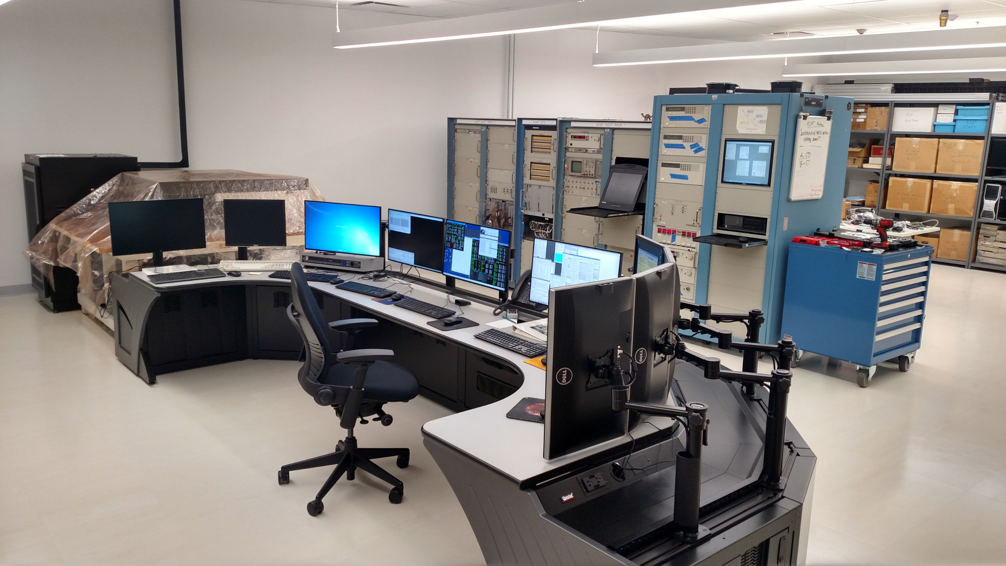
ASVT is a high fidelity hardware- and software-based simulator of Chandra that we use for every OBC software patch and to run team-wide simulations of anomalies and other training scenarios. ASVT is a unique facility in the OCC that stitches together pre-launch flight spares of most key electronic and hardware components in a rack-mounted system. This is integrated with computers to interface with the hardware and fool the system into believing it is the real Chandra up in space orbiting Earth. A key example is the Vehicle Dynamics Simulator (VDS), which simulates the physics of the Inertial Reference Units (sensor) and Reaction Wheel Assemblies (actuators) along with external stimuli such as gravity gradient torques during the Chandra orbit.
Simply keeping ASVT running is a challenge in itself. This facility includes 30-year-old electronics, and nothing lasts forever. Finding replacement parts requires ingenuity, and our intrepid engineer has been known to find components on eBay!
A bold plan in 2016: the ASVT PEA test set
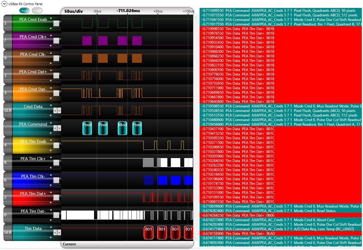
Backing up another year, the program was fortunate to have a flight spare PEA and aspect camera, but as of 2016 they were attached to a 1990’s era PC running an extremely limited development and test utility. This setup had sufficed for an earlier ACA patch that was a relatively simple 73 lines of source code, but we understood that developing and testing complex ACA patches would become a necessity and that having a high-fidelity ACA simulator integrated into ASVT would be hugely beneficial for operations. An audacious plan was hatched to use the existing PEA and build from scratch the hardware and software that would emulate the aspect camera optics, the sky, the CCD, and the real-time readout and interface electronics. This would interface with the ASVT VDS to provide the real-time attitude reference for simulating star light. What added real spice to the project was that we had sparse documentation on the aspect camera electronics—much of the digital communication and timing between the PEA and the aspect camera would need to be reverse engineered from the communication interface using logic probes with custom digital protocol analysis, as well as a lot of ingenuity and patience.
Despite the difficult path, over the next year and a half the plan became a reality, and by Aug 2017 the OCC now had a functioning ACA emulator integrated into ASVT. The initial development was followed by a thorough functional and validation testing effort including detailed comparison with flight data. With that success the PEA test set was operationally certified.
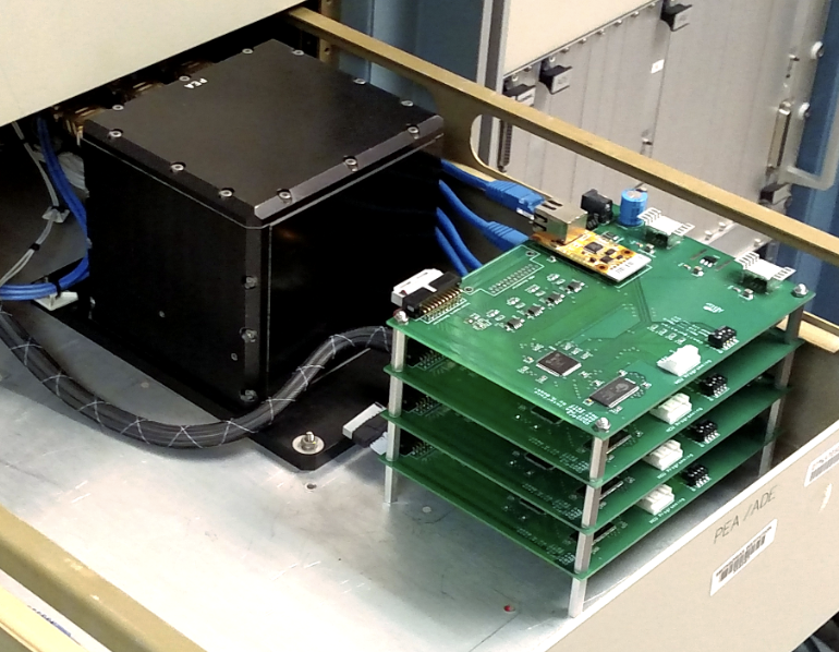
And here is an important point: while you might imagine that the organization that runs one of NASA’s premiere observatories has a deep staff with dozens of engineers, in reality the CXC is a lean team. Even though we emphasize teamwork—and indeed that is critical to the success of Chandra and, in particular, to the dynamic background patch as a whole—we also need to recognize that some mission-changing innovations are largely the work of a single very talented individual with drive and a vision. The ASVT PEA test set, pictured below, is certainly a case in point.
Go Forth and multiply (using integer arithmetic)
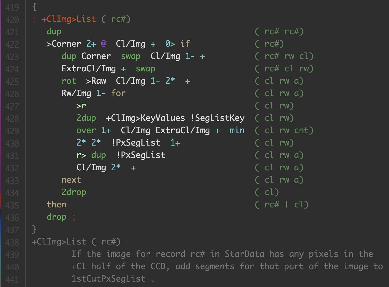
Development of the ASVT PEA test set was an exciting milestone in the journey, but now came perhaps an even more daunting challenge: the actual dynamic background patch development. The PEA software that controls the ACA is written in Forth, a stack-based language that is just barely distinguishable from raw assembly language. The figure below shows one of hundreds of functions from over 6600 source lines of code that comprise the PEA software. The comments on the right in parentheses represent the contents of the stack, which must be carefully tracked through all of the operations. A single mistake here will result in disaster.
The existing PEA software for the Chandra ACA was the evolutionary endpoint of several generations of star tracker code from Ball Aerospace, written largely by a single talented engineer at Ball. This is a single-threaded, real-time control system with severe constraints on available memory (64K RAM, 32K ROM) and processor speed (8 MHz). The available software development environment and debugging capability was primitive by modern standards. Given all that, it is a testament to the original design engineer that the code has functioned quite well over 24 years and that we have identified only a few bugs, none of them critical. That said, the source code is extremely challenging to understand and the documentation could certainly be more helpful. Which leads to the next major endeavor in the journey.
PEA Forth software development kit (SDK)
The dynamic background patch would end up adding 841 lines of source code spread over dozens of places in the code, fundamentally altering the code flow. Not only would the patch update the image processing, but it required new downlink telemetry modes and new PEA command capability. All of these changes needed to be carefully spliced into the existing code by means of a limited set of pre-defined patch hooks. Accomplishing such a major patch required stepping back and writing a full-featured Forth SDK for the PEA, essentially from scratch. This would include an interactive web-based source browser with symbol navigation, a debugger, a disassembler, and a memory browser and mapper. Finally, in order to run unit tests on individual functions, we implemented the ability to run sections of the code on a PC independent of the PEA hardware.
Nobody loves testing
Going into this project, we knew one thing. To paraphrase Matt Damon’s character in The Martian, we’re going to have to test the s*** out of this. Why? Because it strikes at the very heart of Chandra's Pointing Control and Aspect Determination (PCAD) system. Most of the time Chandra is in Normal Pointing Mode where it relies on the measured positions of 5 to 8 guide stars, along with gyroscope rate data, to establish an absolute 3-axis attitude on the celestial sphere. These star positions are captured by the ACA every 2.05 seconds and provided to the On-Board Computer, where they are used in a Kalman filter to optimally estimate the attitude and effective gyro bias vector.
First and foremost the OBC must maintain positive spacecraft attitude control and execute the Lissajous dither pattern for effective science and to protect the X-ray instruments. Once Chandra is done observing a target, it is time to maneuver to the next target. This must be done with an accuracy of better than 2 arcmin over maneuvers up to 180 degrees. Any error in the estimated attitude (in particular the roll about the long axis of Chandra) translates directly into a spatial error at the end of the maneuver.
Nobody really loves testing, but an extremely thorough test program was the only way we could allow this patch to fly. If you are a normal person you might find even the bulleted list below of the testing program a bit tiresome to read. We hope that this gives you a flavor of the effort required for this patch, highlighting that each of these bullet points are the tip of an iceberg that could translate to hundreds of pages of documentation and a like number of hours to develop and execute.
- Performance Testing: ensure that the new code would not cause any overruns in the real-time control loop. This required its own mini-patch to implement.
- Algorithm Validation Testing: using tens of thousands of simulations run on a computing cluster, ensure that the algorithm works over a wide range of scenarios and parameters.
- Unit Testing: verify functionality of individual functions.
- Visual Inspection of Patch Code: verify the compiled machine instructions for certain low-level functions.
- Dump and Compare Testing: verify the hex command patch uplink is correct.
- Functional Verification Testing of Patch Requirements: detailed high-level functional tests using ASVT of each of the 18 patch requirements.
- Regression Testing: verify that untouched functionality provided by the PEA still works as expected.
- System Testing: run a set of simulated command loads spanning several days with a variety of stressing observations.
- Code Test Coverage: verify all branches of the new patch code are exercised by at least one test case.
- Uplink Simulation: run a full-team on-console simulation of the entire uplink procedure.
The real deal: on-orbit patch performance
After successfully uplinking the dynamic background patch on May 18 and verifying the initial performance improvement for an hour, we started a waiting game for the slow trickle of real observations using the new PEA software. A key metric we examine are the residuals (telemetered – predicted) in the centroids reported by the PEA. We can get an estimate of the predicted star position on the CCD using the on-board estimated attitude which optimally combines all 5 to 8 stars plus the gyroscope rate data. While a bit circular, this estimate is a good approximation in the absence of truth data. Looking at the 95th percentile radial centroid residuals tells us about the worst-case performance during an observation, which is a primary concern since that is the most likely path to an ACA-related safing action like Chandra experienced in 2017.
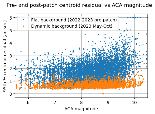
After a few weeks of waiting, the first piece of good news was the absence of anything unusual in mission operations. By all accounts it was business as usual. Then the moment of truth came with a plot comparing pre- and post-patch residuals, and it was spectacular! Fast-forward five months (October 2023) and the results are shown below. The blue dots show centroid residuals using the original flat background algorithm (spanning about a year and a half prior to the patch implementation) and the orange dots are those from after the dynamic background patch. The improvement is obvious and remarkable.
Turning back the clock, with a caveat
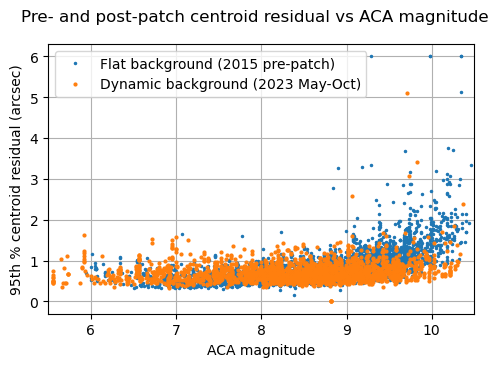
A different way to characterize the performance improvement is to think of the patch as a time machine that restores the ACA to a time in the past when the CCD was in a happier place: less damaged and cooler. The plot below shows that the patch is almost like reversing 8 years of degradation! The performance now in 2023 for science observations is similar to how it was in 2015; in fact, things are even a little better now at the faint magnitude end.
There is an important caveat in this rosy picture. The dynamic background algorithm relies on sampling the edge pixels at the start of an observation, which requires that the star is tracked well enough to remain roughly centered in the image readout window for about 500 seconds. During this burn-in period the dynamic background improvement does not apply, and for very faint stars the tracking may be unreliable. In practice this situation is rare, but we need to take it into consideration for operations mission planning. Instead of planning like it was 2015 again, we use a more conservative approach of only applying the 2015 performance to the faintest two stars in a star catalog. The brighter stars provide an anchor to ensure safe operations.
Another key point is that this patch only improves the ability of the ACA to track guide stars. An equally important part of the operations picture is acquiring stars following a maneuver. This is done by a very different process that is not helped by the patch. In some cases finding sufficiently bright acquisition stars can be a constraint, but we do have a way to mitigate this by sacrificing observing efficiency.
The future looks bright
With the ACA PEA test set and SDK now available as mature tools, we are already thinking about the next patch, possibly to improve the star acquisition performance. We have also made significant progress on a platform that runs the actual PEA code within an environment that emulates the PEA hardware, thus allowing simulations to run more flexibly and with easy access to the internal data of the software algorithms.
From the observer’s perspective, with the dynamic background patch in place and operating smoothly, we are looking forward to years of Chandra science observations with less impacting constraints from the ACA.
In memoriam
This article is dedicated to the memory of Dr. Eric Martin, who made fundamental contributions to the dynamic background patch. Eric's career with TRW/Northrop Grumman spanned almost 40 years. After working on several other TRW projects, Eric joined the AXAF/Chandra development team at Space Park, working on PCAD subsystem design, coding, and analysis efforts. He transitioned to the OCC in Cambridge to support launch activities, and he had been an integral member of the Flight Operations Team since then. He wore many hats on the team, contributing to a wide range of topics and mission achievements. His deep knowledge of the PCAD system and software will be sorely missed, but in particular we will remember his can-do attitude, resilience in high-pressure anomalies, and personal stories of his beloved dogs and chasing eclipses around the world.