Next: 10. vtpdetect Parameters & Up: The Detect Reference Manual Previous: 8. Running vtpdetect Contents
Reprinted with permission from Detecting Structure in Two Dimensions Combining Voronoi Tessellation and Percolation by H. Ebeling & G. Wiedenmann, Physical Review E, 47, 704, 1993. Copyright 1993. The American Physical Society. The version herein has been edited.
The figures from the original paper no longer exist electronically; the ones given in this chapter are reproductions.
Conventional source-detection algorithms in high-energy astrophysics and other fields mostly use spherical or quadratic sliding windows of varying size on two-dimensionally binned representations of spatial event distributions in order to detect statistically significant event enhancements (sources) within a given field. While this is a reasonably reliable technique for nearly pointlike sources with good statistics, poor and extended sources are likely to be incorrectly assessed or even missed, as the calculations are governed by non-physical parameters like the bin size and the window geometry rather than by the actual data. The approach presented here does not introduce any artificial bias but makes full use of the unbinned two dimensional event distribution. A Voronoi tessellation on a finite plane surface yields individual densities, or fluxes, for every occupied pixel. The distribution of the densities allows us to determine the contribution from a random Poissonian background field (noise). The application of a non parametric percolation to the tessellation cells exceeding this noise level leads directly to a source list which is free of any assumptions about the source geometry. High-density fluctuations from the random background field will still be included in this tentative source list but can be eliminated in most cases by setting a lower threshold to the required number of evens per source. Since no finite-size detection windows or the like have been used, this analysis automatically yields straightforward fluxes for every source finally accepted. The main disadvantage of this approach is the considerable CPU time required for the construction of the Voronoi tessellation--it is thus applicable only to either small fields or low-event density regions.
Many physical applications involve procedures which, in a way, can be called source-detection algorithms. Although we will use the most obvious case of a two-dimensional spatial event distribution to demonstrate the advantages of the technique described in the following, it is, in principle, applicable to any problem where significant density enhancements are sought in a two-dimensional parameter space ( not necessarily spatial).
In high-energy astrophysics spatially resolved observations of astronomical objects often yield a few or even single photon counts per detection cell to begin with. The raw data provide the highest attainable spatial resolution which is limited by the detector hardware only; count statistics, on the contrary, can be extremely poor, especially for weak extended sources.
These poor statistics are the major handicap of conventional source detection algorithms which make use of a locally determined background in order to flag possibly significant density enhancements in the photon distribution. It is this concept of a local search which often makes the introduction of a coarser data binning inevitable in order to improve the count statistics locally at the expense of spatial accuracy. So-called sliding windows (mostly rectangular), of varying size are then moved across the binned distribution marking the positions where the count rate in the central part of the window exceeds the value expected from the background determined in the outermost regions of the window by a certain predetermined factor.
Using this technique it is clear that the decision whether a source is regarded as significant or not will be affected by several purely artificial parameters namely
This well-known flaw is overcome only partially by an additional commonly used detection algorithm which utilizes the results of the local detect procedure only in as much as it clips the detected sources and then computes a global background map from the remainders. A maximum likelihood (ML) routine is then used to find sources in the background subtracted distribution. However, as the ML algorithm has to assume a model profile (most applications use Gaussian distributions) to fit to the data the dependency of the decision process on an artificially fixed geometry persists.
The method we will describe in the following shows none of these
shortcomings as, firstly, it does not sort the photons into artificial
bins but rather works on the raw data globally, thus being
limited only by the detector's resolution, and, secondly, it does not
assume any particular source geometry for the detection
process. Because of the great deal of CPU time required it should be
used only on rather small datasets when searching for sources which
are characterized by a low density of occupied pixels. As a sample
event distribution, photon counts as detected by the xray telescope
aboard the Rosat satellite in a
![]() field of the
sky will be used.
field of the
sky will be used.
The actual procedure can be briefly summarized as follows.
(1) The Voronoi tessellation for the original raw photon distribution is computed.
(2) The cumulative distribution of the inverse areas of the resulting Voronoi cells is compared with that expected for a random Poisson distribution. A cutoff value for the photon density parameterizing the global background is determined.
(3) A spatial percolation algorithm is run on the individual cells, grouping cells (i.e., photons) exceeding the background density into sources.
(4) The minimal number of photons required for a true source is computed in order to discriminate against background fluctuations.
For a given two-dimensional distribution of points (often also called atoms; in our application: photons) the Voronoi tessellation [1] is a uniquely defined set of convex cells, each of which encloses one and only one of these points. Depending on the implied boundary conditions the entire set of cells covers either the whole plane or just the area enclosed by the polygon defined by the outermost points of the distribution. In any case there are neither gaps nor overlaps between adjacent Voronoi cells. The algorithm used here for the construction of this tessellation is a two-dimensional adaption of the recipe described by Tanemura, Ogawa, and Ogita [2] for three dimensions.
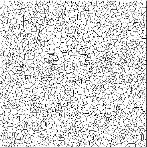
We use open boundaries on a plane, finite-area surface, where the constructibility of the out most cells is guaranteed by restricting the tessellation to the central region of the area actually covered by the photon distribution. For the application presented in the following we found a confinement to the central 81% of the field area to be a good choice. Figure 9.1 illustrates the resulting cell distribution for the tessellation of a sample set of 2000 randomly positioned points.
Let us assume for a moment that this random distribution was an actual measurement of some background radiation field: a physically interesting quantity would then not be the area assigned to each photon by the tessellation but rather the distribution of fluxes, i.e., detector counts per time interval and unit area, in order to establish a background level to compare to the fluxes of potential sources.
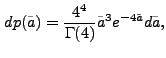
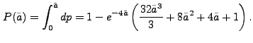
We are not aware of an analytical derivation of the cell area distribution function for randomly positioned points following Poissonian statistics; numerical simulations [3], however, suggest that the empirical results converge towards the differential probability distribution
Note that although the purely random photon distribution appears to reveal considerable structure in Fig. 9.1, which is what a local detection algorithm would look for, the cumulative flux distribution representing a global property of the data looks extremely smooth as statistical fluctuations tend to cancel out on a larger scale.
![\begin{figure}\centering
\includegraphics*[width=12cm]{plots/vtp_theory_fig2.ps}
\end{figure}](img118.gif) |
However, if sources are located within the field of view, a significant
deviation from the Poissonian curve is observed. In simulated
distributions, three sources of different extent were put on top of
2000 background photons like the ones shown in
Fig. 9.1. Each of the three
artificial sources consists of 200 photons in a spatial Gaussian
distribution. The width of the Gaussian varies, however, from
![]() (Fig. 9.4) through
(Fig. 9.4) through
![]() to
to
![]() (Fig. 9.5);
no figure is given for the
(Fig. 9.5);
no figure is given for the
![]() case. Whereas the first
two sources are rather compact despite their extent, the third one is
extremely extended and poses a true challenge to any source-detection
algorithm. The resulting flux
distributions, however, are in all three cases clearly inconsistent
with the random background curve which was fitted to the data in the
background-dominated low-flux range where
case. Whereas the first
two sources are rather compact despite their extent, the third one is
extremely extended and poses a true challenge to any source-detection
algorithm. The resulting flux
distributions, however, are in all three cases clearly inconsistent
with the random background curve which was fitted to the data in the
background-dominated low-flux range where
![]() . Extensive simulations showed this range to yield the highest
accuracy and reliability in the determination of the fit parameter,
the total number of background photons. For all three examples this
number, as determined by the fit, is within 2% of the true value.
. Extensive simulations showed this range to yield the highest
accuracy and reliability in the determination of the fit parameter,
the total number of background photons. For all three examples this
number, as determined by the fit, is within 2% of the true value.
![\begin{figure}\centering
\includegraphics*[width=12cm]{plots/vtp_theory_fig4.ps}\end{figure}](img124.gif) |
![\begin{figure}\centering
\includegraphics*[width=12cm]{plots/vtp_theory_fig5.ps}\end{figure}](img126.gif) |
From the residuals presented in Fig. 9.6 and
Fig. 9.7, an upper flux limit for background
contributions can be determined in order to
allow the separation of high-flux from low-flux regions in the
subsequent percolation. This cutoff is established at the flux value
where the background-corrected cumulative distribution
![]() [or
[or
![]() ] reaches its minimal value,
i.e., where the measured flux
distribution starts to rise faster than would be expected for a purely
random photon distribution. Note that for all three examples this
cutoff excludes more than two-thirds of the photons from the
percolation process.
] reaches its minimal value,
i.e., where the measured flux
distribution starts to rise faster than would be expected for a purely
random photon distribution. Note that for all three examples this
cutoff excludes more than two-thirds of the photons from the
percolation process.
Apart from the Voronoi cells in high-flux regions around the sources we are actually looking for, fluctuations in the random background will of course also be found in the upper end of the flux distribution. Most of these fluctuations consist, however, only of a couple of adjacent cells and can therefore be eliminated by means of a percolation algorithm accepting exclusive sources containing more than a certain minimum number of photons.
What is usually meant by "percolation'' (often called
"friends-of-friends'') algorithms is the search for close groups of
objects in a two- or three-dimensional distribution using a maximally
allowed separation
![]() between each two of these objects as
the only parameter to be set beforehand. Starting at any point, all
neighboring objects closer to the starting point than the specified
maximal distance are taken to be members of the agglomeration and
become starting points in the next iteration themselves. Algorithms of
this sort are often used as source-detection algorithms in their own
right, the main difficulty being the choice of a suitable value for
between each two of these objects as
the only parameter to be set beforehand. Starting at any point, all
neighboring objects closer to the starting point than the specified
maximal distance are taken to be members of the agglomeration and
become starting points in the next iteration themselves. Algorithms of
this sort are often used as source-detection algorithms in their own
right, the main difficulty being the choice of a suitable value for
![]() which determines the scale at which sources are found.
which determines the scale at which sources are found.
Fortunately, the percolation algorithm used here does not need any
distance parameter;
![]() is, in a way, replaced by the flux
cutoff determined from the comparison between the flux distributions
for the data and a random background field. As this cutoff value
corresponds to an area (namely that of the Voronoi cells) rather than
a linear distance, it makes the percolation far more flexible and less
prone to erroneously taking fluctuations for true sources
is, in a way, replaced by the flux
cutoff determined from the comparison between the flux distributions
for the data and a random background field. As this cutoff value
corresponds to an area (namely that of the Voronoi cells) rather than
a linear distance, it makes the percolation far more flexible and less
prone to erroneously taking fluctuations for true sources
For the simulation example discussed in the previous sections, the percolation found, in fact, more sources per field (consisting of more than ten photons each) than just the one we put in. As the background radiation has entered only implicitly so far, namely in the flux threshold for the percolation, we still have to correct the source counts (i.e., the number of photons assigned to each source) for background photons. Knowing the total area covered by each source from the Voronoi tessellations, a background correction can be applied by simply subtracting the number of background photons statistically expected in the same area.
In all three cases the detections of both the simulated sources are accompanied by spurious detections in the field of background photons consisting of up to 12.3 photons (number background corrected). In general one more step is thus required in order to discriminate against random fluctuations, namely the establishment of a value for the minimal number of photons required for a real source.
The normalized number of sources caused by random fluctuations in the background field can be written as
where
![]() is the flux cutoff value used to separate
high- from low-flux events for the percolation and
is the flux cutoff value used to separate
high- from low-flux events for the percolation and
![]() is the
number of photons above the background level in the fluctuation
source.
is the
number of photons above the background level in the fluctuation
source.
![]() in Eq.( 9.3) is normalized to
the total number of background photons in the tessellation area,
in Eq.( 9.3) is normalized to
the total number of background photons in the tessellation area,
![]() so that the actual number of random sources of size
so that the actual number of random sources of size
![]() in a given field is
in a given field is
In the range
![]() , which is where the
flux cutoff value is found to lie for almost any event distribution,
both
, which is where the
flux cutoff value is found to lie for almost any event distribution,
both
![]() and
and
![]() are reasonably well described by
linear functions of
are reasonably well described by
linear functions of
![]() . Least squares fits
yield
. Least squares fits
yield
Obviously, the statistically expected number of fluctuation sources
containing at least
![]() photons above the mean background
value is then given by
photons above the mean background
value is then given by
Requiring that no random source be detected in our fields at the 90%
confidence level we find values for
![]() of 9.1, 13.2, and
13.2 photons, respectively, for our three simulated sources from
Eq. (9.4), thus eliminating all of the additional sources
and leaving only the central "true'' source.
of 9.1, 13.2, and
13.2 photons, respectively, for our three simulated sources from
Eq. (9.4), thus eliminating all of the additional sources
and leaving only the central "true'' source.
Finally, it is interesting to take a closer look at the sources' characteristics as determined by the algorithm. The algorithm is not biased towards preferential detection of spherical sources or sources of any other fixed geometry. This is the main advantage in comparison with conventional window algorithms.
The accuracy of the source positions, which are computed as the
flux-weighted mean values of the individual photon coordinates,
depends both on extent and brightness of the object. For our example
the deviation of the detection position from the coordinates specified
in the simulations amounts to
![]() ,
,
![]() , and
, and
![]() (in order of
ascending extent) which is comparable to the accuracy attained with
conventional algorithms on binned data.
(in order of
ascending extent) which is comparable to the accuracy attained with
conventional algorithms on binned data.
As for the total source flux, we find background-corrected values of 196.8, 197.8, and again 196.8 photons, which is to be compared to the actual number of 200 photons put into each source in the simulation. In all cases the source's flux was thus found to be within 2% of the true value.
Leaving the simulated and entering the real world we applied the
algorithm to a Rosat x-ray image which was taken during the
satellite's six months all-sky survey. The
![]() field looks almost blank and in fact no source was found in the field by
conventional source-detection techniques.
field looks almost blank and in fact no source was found in the field by
conventional source-detection techniques.
The reason why we chose this particular field is the fact that it is centered on the optical position of a nearby cluster of galaxies. The hot gas trapped in the potential well of a cluster being the source of extended x-ray emission one would expect to see an enhancement in the photon flux on a scale of about half a degree corresponding to the angular size of the cluster core
The algorithm run on these data is different from the one described above only in as much as the exposure time which is slightly varying over the field is taken into account by weighting the Voronoi cell areas with the local exposures, thus converting inverse areas into true fluxes.
The expected emission is indeed detectable with the presented algorithm. Three sources are found: the upper one contains 34.5 photons more than would be expected from the background field in the same area and is thus clearly a real detection. (The probability for finding a fluctuation exceeding the background by more than 19.8 photons is less than 10% for this field.) The central extremely extended source is actually split into two, the smaller of which forms the northern bulge and consists of 21.9 photons. All the rest of the central emission is interconnected to build one large source with a total of 179.6 "true'' photons and coincides perfectly with the position of the cluster core as it is determined from the galaxy distribution.
The source-detection technique described above is widely applicable to all sorts of two-dimensional event distributions. Although we have restricted ourselves to the specific problem of detecting sources in a homogeneous background field, the method can be used quite generally to find any kind of structure embedded in a Poissonian background field. The advantages of our alternative approach which bears importance for a great variety of applications related to pattern recognition and image processing are the following:
So far we have only considered a background following Poissonian statistics. As our method only uses the deviation of the cumulative probability distribution from the expected noise distribution it should, however, also be possible to discern structure from a correlated background provided that the probability distribution of the Voronoi cells for this background is known.
The algorithm's main advantage is its ability to detect sources of almost arbitrary extent, but care should be taken to provide a large enough field in order to allow the background fit to be as accurate as possible. If fields of very high source densities are studied, problems may arise by the tendency of the percolation algorithm to leave filamentary bridges between nearby adjacent sources, leading to errors in the computation of both the position and the flux of the source. In cases where potential sources are known to be rather compact and bright, one should, for CPU time's sake, rely on conventional detection algorithms unless besides the sources detection the determination of its flux is an equally important issue.
The authors would like to thank Valentin Demmel who provided much of the software this algorithm was built upon; Hans Böhringer and Gregor Morfill are thanked for stimulating discussions. Last, but not least, we are grateful to the Rosat SASS team at MPE for supplying the x-ray data used to illustrate a typical application.
[1] Voronoi, G. and Angew, J. Reine. 1908, Math. 134, 198
[2] Tanemura, M., Ogawa, T., and Ogita, N. 1983, J. Comput. Phys. 51, 191
[3] Kiang, T. 1966, Z. Astrophys. 64, 433
Additional References:
Ebeling et al. 1996, MNRAS, 281, 799
Scharf et al. 1997, ApJ, 477, 79
Jones et al. 1998, ApJ, 495, 100

![\begin{figure}\centering
\includegraphics*[width=12cm]{plots/vtp_theory_fig3.ps}
\end{figure}](img119.gif)
![\begin{figure}\centering
\includegraphics*[width=12cm]{plots/vtp_theory_fig6.ps}\end{figure}](img129.gif)
![\begin{figure}\centering
\includegraphics*[width=12cm]{plots/vtp_theory_fig7.ps}\end{figure}](img130.gif)
![$\displaystyle N_{\rm src,fluct}(\tilde{f}_{\rm min}, \geq n_{\rm ph}) = N_{\rm ...
...{\rm min},0)}{b(\tilde{f}_{\rm min})} \exp [-b(\tilde{f}_{\rm min})n_{\rm ph}].$](img145.gif)