Chapter 3
Offset Pointing, Visibility, and other Constraints
3.1 Introduction
This chapter gathers together several topics pertaining to observation
planning, irrespective of focal-plane instrument and grating
configuration, to serve as additional guidelines for the preparation of
proposals. Many of these topics are automatically addressed by the target visibility
interface webtool (ProVis; https://cxc.harvard.edu/cgi-bin/provis/provis_load.cgi) or the observation
visualizer software (ObsVis; https://cxc.harvard.edu/obsvis/) available as part of the Chandra Interactive Analysis of Observations (CIAO) software. The intention
here is to familiarize the user with these various
observation-planning topics.
3.2 Offset Pointing
The offset pointing convention for Chandra is that a negative offset of
a coordinate moves the image to more positive values of the coordinate
and vice-versa. Examples of offset pointings of the ACIS instrument
are shown in Figure 3.1. Examples using the HRC are
shown in Figures 3.2 and 3.3.
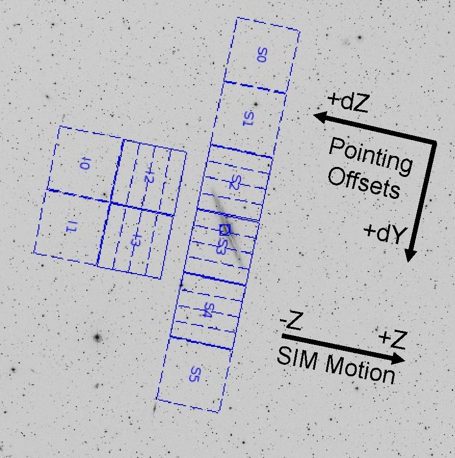
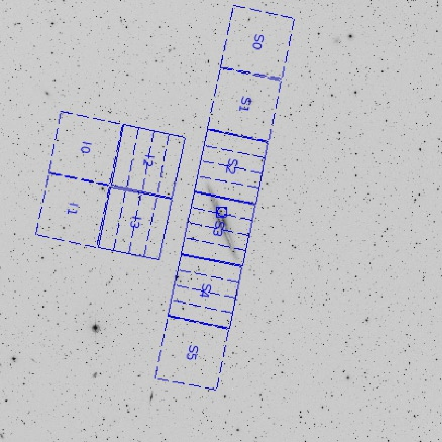
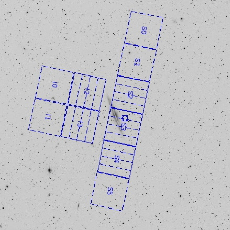
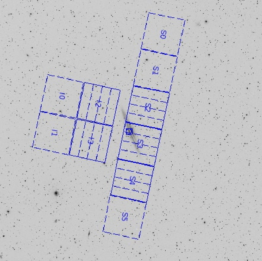
Figure 3.1: Image (1°×1°) created with ObsVis shows the ACIS field-of-view
overlaid on the optical image of the galaxy NGC 891. North is up and
east is to the left. The roll angle—the angle between celestial north and the spacecraft −Z
axis projected on the sky, as measured positive from N through W—shown is
100°. Five chips are turned on (solid outlines, with dashed node
boundaries shown) and five off (dashed chip outlines). The
circle-in-a-square symbol shows the aimpoint. Upper
left panel: Target is centered at the nominal ACIS-S
aimpoint. The (dY,dZ) coordinate system used to define pointing
offsets is also shown (refer to Figure 1.1 for a general
view of Chandra spacecraft coordinates), as well as the SIM Z motion
direction used to define the location of the aimpoint on the
detector (see Figure 1.2). In the case shown, (dY,dZ)=(0,0).
Upper right panel: The target has been offset by
1.5 arcmin in the negative Y direction, i.e., a (dY,dZ) target
offset of (−1.5 arcmin, 0). Lower left panel: The
target has been offset by 3 arcmin in the negative Z direction,
i.e., (dY,dZ)=(0, −3 arcmin). Lower right panel:
No target offset has been applied, i.e., (dY,dZ)=(0,0), but a SIM Z
motion of +3 arcmin has been applied. Note that in the latter two
cases (lower left and lower right) the target is in the same place
on the detector, but in the lower right case the aimpoint moves with
the target, keeping the target near the optical axis and the
aimpoint for optimal imaging quality.
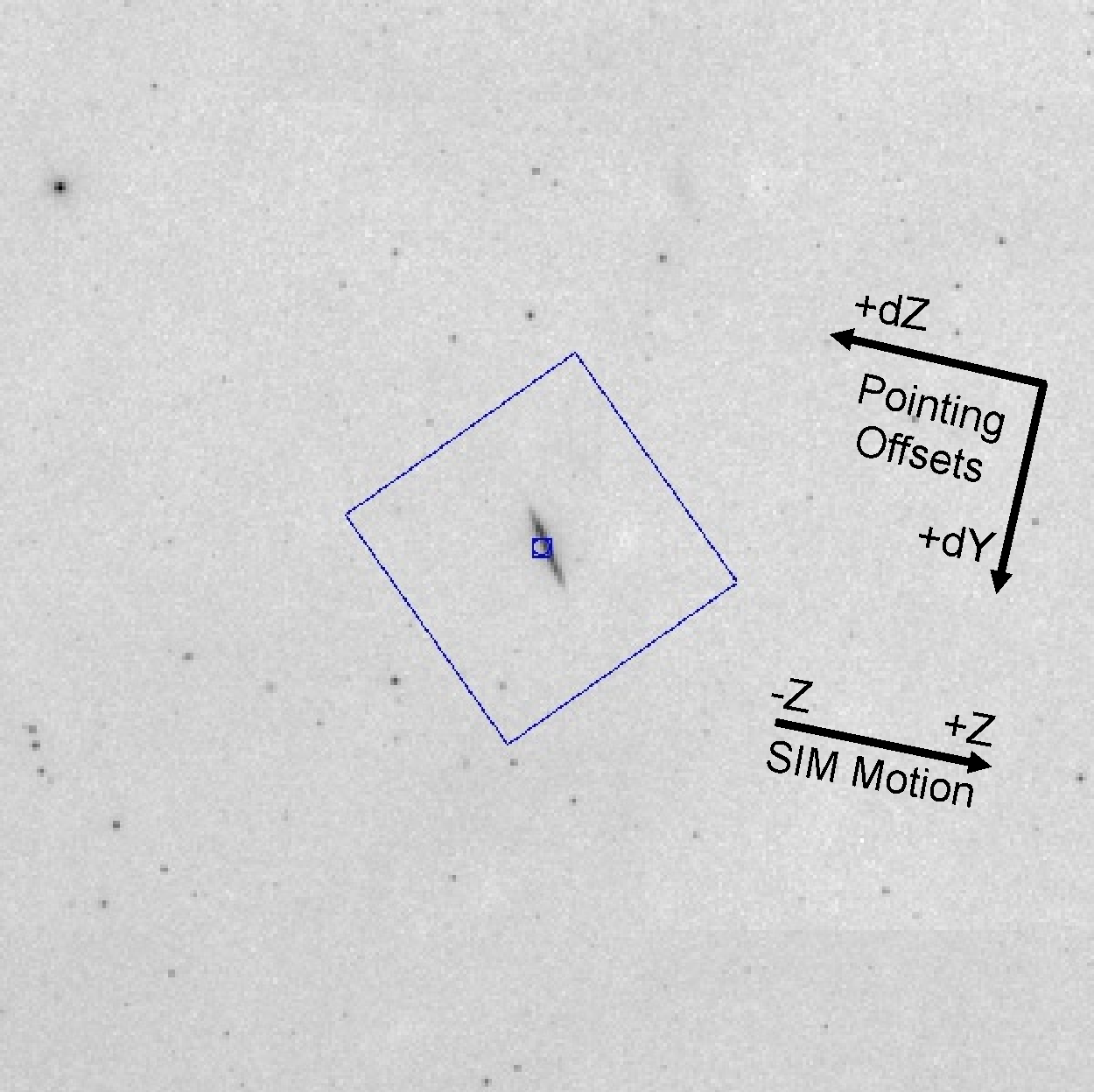
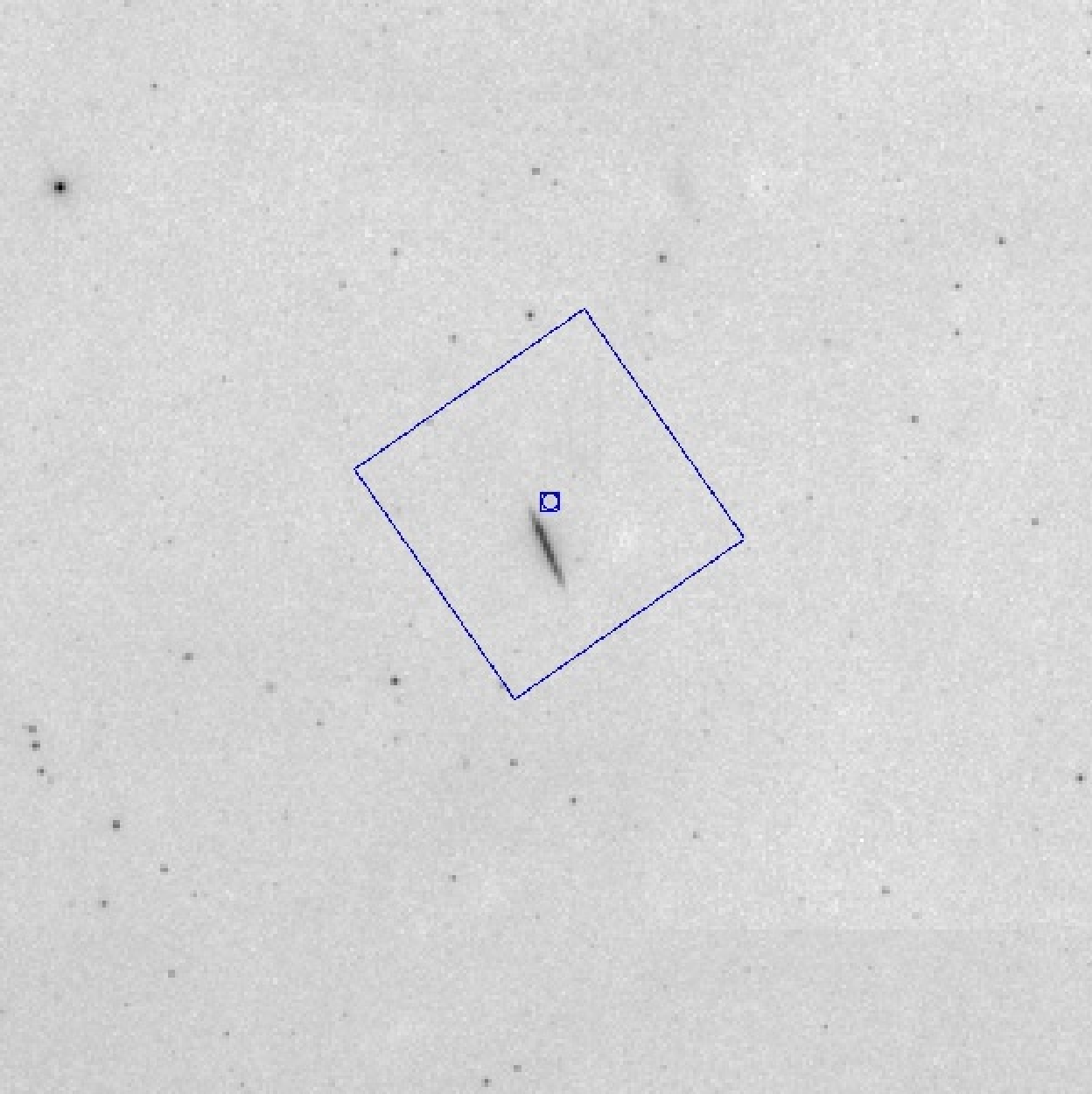
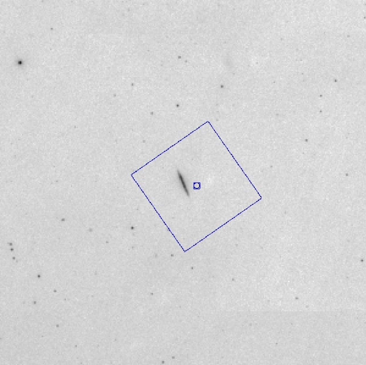
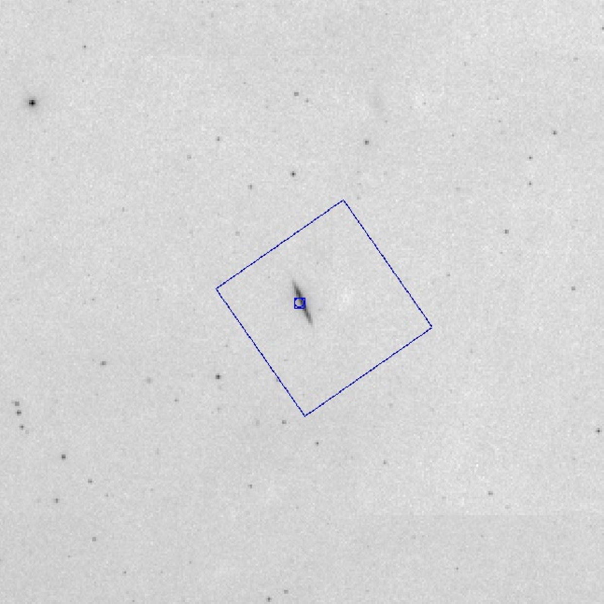
Figure 3.2: Offset pointing with HRC-I on a 2deg×2deg image of NGC 891; orientation
and roll angle are the same as in Figure 3.1.
Upper left panel: Target is centered at the nominal HRC-I aimpoint. The (dY,dZ)
coordinate system used to define pointing offsets is also shown, as
well as the SIM Z motion direction used to define the location of the
aimpoint on the detector. Upper right panel: The target has been
offset by 5 arcmin in the negative Y direction, i.e., a (dY,dZ) target
offset of (−5 arcmin, 0). Lower left panel: The target has been
offset by 5 arcmin in the negative Z direction, i.e., (dY,dZ)=(0, −5
arcmin). Lower right panel: No target offset has been applied, i.e.,
(dY,dZ)=(0,0), but a SIM Z motion of +5 arcmin has been applied. Note
that in the latter two cases (lower left and lower right) the target
is in the same place on the detector, but in the latter case the
aimpoint moves with the target.
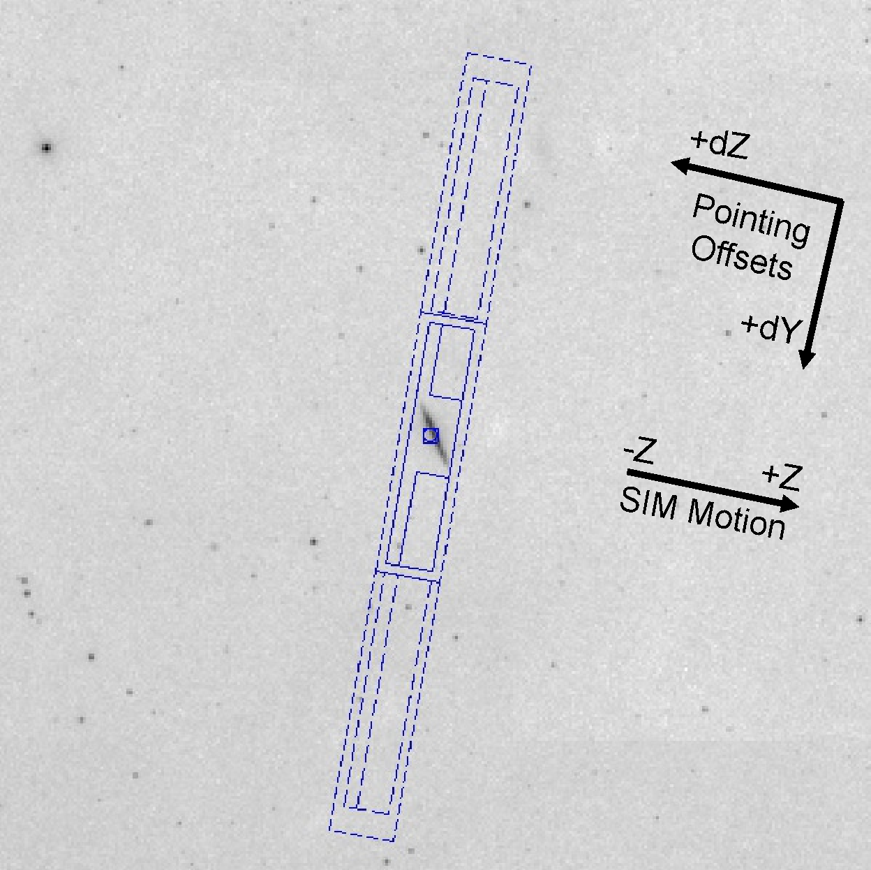
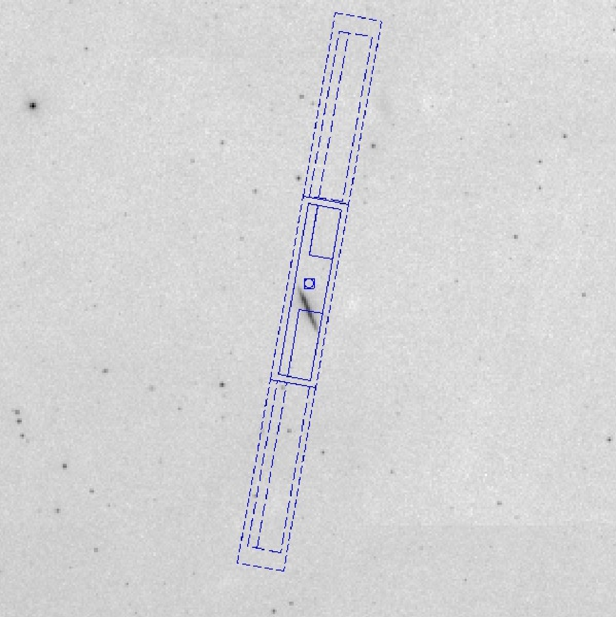
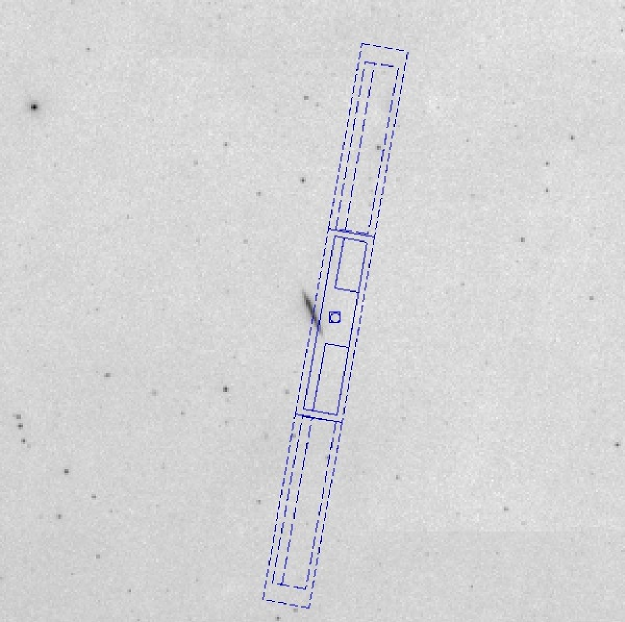
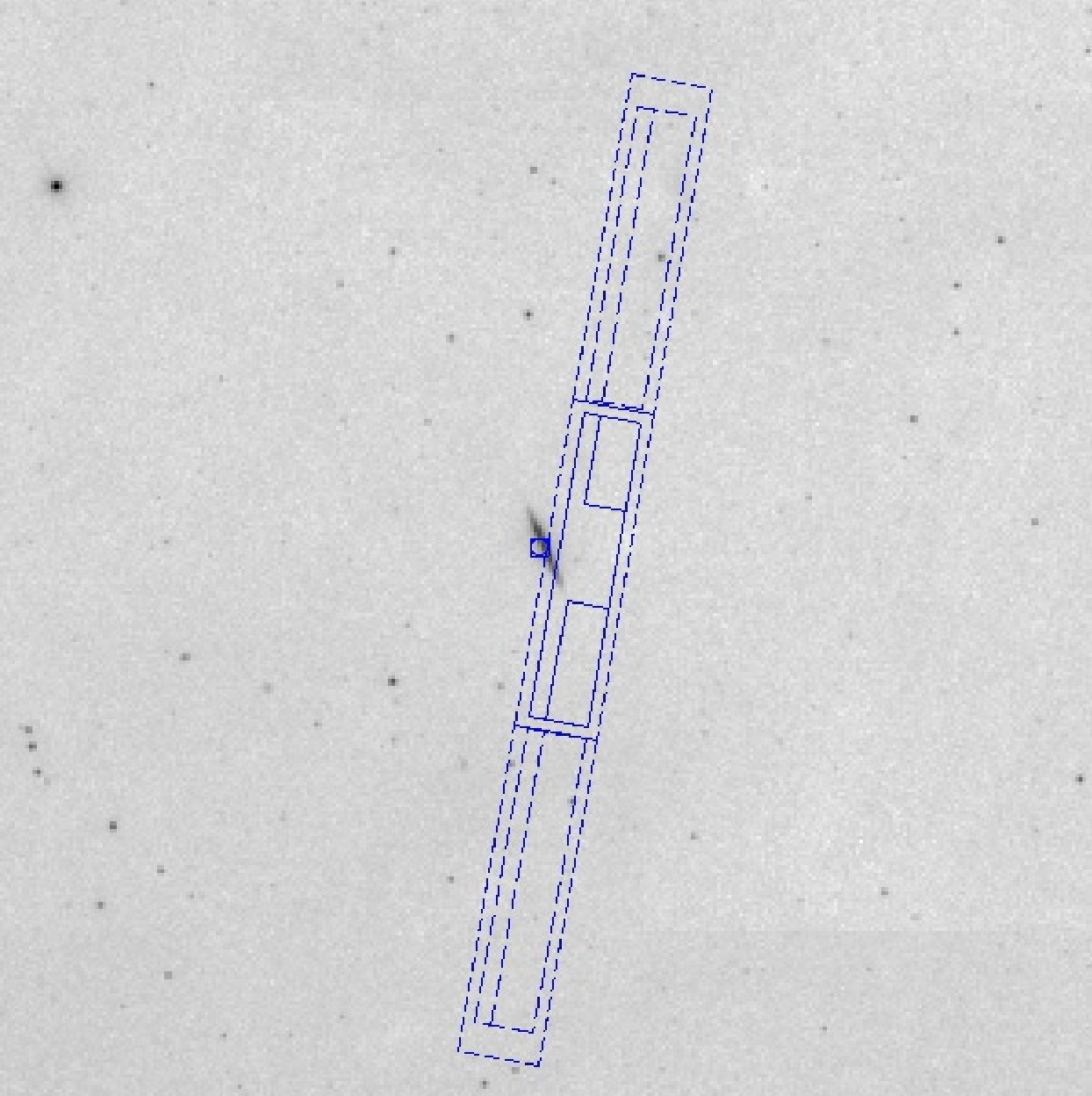
Figure 3.3:
Offset pointing with HRC-S on a 2deg×2deg image of NGC 891; orientation
and roll angle are the same as in Figure 3.1.
Upper left panel: Target is centered at the nominal
HRC-S aimpoint. The (dY,dZ) coordinate system used to define pointing
offsets is also shown, as
well as the SIM Z motion direction used to define the location of the
aimpoint on the detector. Upper right panel: The
target has been
offset by 5 arcmin in the negative Y direction, i.e., a (dY,dZ) target
offset of (−5 arcmin, 0). Lower left panel: The
target has been
offset by 5 arcmin in the negative Z direction, i.e., (dY,dZ)=(0, −5
arcmin). Lower right panel: No target offset has
been applied, i.e.,
(dY,dZ)=(0,0), but a SIM Z motion of +5 arcmin has been applied. Note
that in the latter two cases (lower left and lower right) the target
is in the same place on the detector, but in the latter case the
aimpoint moves with the target. Note also that, as shown in the lower
two panels, it is quite possible to use offsets to move the target
position entirely off a detector.
3.3 Visibility
There are a number of factors that limit when
observations can be performed. These are discussed in the
following subsections.
3.3.1 Radiation Belt Passages
High particle-radiation levels are encountered as the Observatory
approaches perigee. Data acquisition ceases whenever certain
particle-radiation thresholds are exceeded. A working number for the
altitude at which this takes place is about 60,000 km. Cessation of
observations and protection of the instruments in regions of high
radiation results in approximately 25% of the 63.5 hour Chandra orbit
being unusable.
3.3.2 Avoidances
The following constraints are necessary to ensure the health and
safety of the spacecraft and science instruments. Proposals which
violate these constraints may be rejected.
- Sun avoidance: viewing is restricted
to angles larger than 46.2 deg from the center of the Sun. This
restriction makes about 15% of the sky inaccessible on any given
date, but no part of the sky is ever inaccessible for more than 3
months. This constraint cannot be overridden.
- Moon avoidance: viewing is restricted to angles larger than 6
deg from the limb of the Moon. This restriction makes less than
1% of the sky inaccessible at any time. This avoidance can be waived,
but at the price of a reduced-accuracy aspect solution (see
Chapter 5).
- Bright Earth avoidance: viewing is restricted to angles larger
than 10 deg from the limb of the bright Earth. This restriction
makes less than 5% of the sky inaccessible at any time, but there are
certain regions which can only be viewed, continuously, for up to
about 30 ks. The avoidance can be waived, but at the price of a
reduced-accuracy aspect solution (see Chapter 5).
Figure 3.4 illustrates the point that the Earth
avoidance region is nearly stationary; this
is a consequence of the combination of high elliptical orbit and
the cessation of science data acquisition during radiation belt
passages. This partially blocked region moves several degrees per
year, reflecting the evolution of the orbital elements.
The greatest amount of observing time is available in the vicinity of
apogee, when the satellite moves most slowly and Earth and its
avoidance zone occupy an approximately stationary location on the sky,
visible in Figure 3.4 as the extension to the south of the Sun avoidance band.
3.3.3 Roll Angle Constraints
The spacecraft and instruments were designed to take advantage of the
Observatory having a hot and a cold side. Thus, the spacecraft is
preferentially oriented with the Sun on the −Z side of the X-Y
plane, where +X is in the viewing direction, the Y-axis is
parallel to the solar panel axes, and +Z is in the direction of the
ACIS radiator (see Figure 1.1). In this orientation
there is only one "roll angle" (rotation about the X-axis, defined positive west of north) for which the solar panels can be
rotated so that they are directly viewing the Sun—the nominal roll
angle. Small deviations ( ∼ deg) from the nominal roll angle
may be allowed, depending on the viewing geometry. The roll-angle
constraint imposes further visibility restrictions. These restrictions can also be
evaluated with the ProVis tool.
 Figure 3.4: The Chandra visibility showing contours of fractional visibility
averaged over the 12-month interval of Cycle 28. The darker the shade
of gray, the lower the visibility.
Figure 3.4: The Chandra visibility showing contours of fractional visibility
averaged over the 12-month interval of Cycle 28. The darker the shade
of gray, the lower the visibility.
3.3.4 Thermal Constraints
As the spacecraft has aged, its thermal properties have gradually changed. Degradation of its reflective multilayer insulation means that the Sun-facing side of the satellite now heats more rapidly, and the spacecraft as a whole operates at higher temperatures than earlier in the mission. Steps have been taken to reduce internal sources of heating. However, the thermal limits of the various spacecraft subsystems are an increasingly important factor in planning operations.
The solar pitch angle (i.e., the angle between the viewing direction and the direction to the Sun) affects which subsystems heat or cool during any given observation. Figure 3.5 shows the solar pitch sensitivity of various spacecraft components. Restrictions on the operating temperatures of these components limit how long the spacecraft can maintain a given pitch angle, and it is often necessary to plan operations such that components heated during one observation can cool during (or in some cases before) the next. The thermal restrictions on the various subsystems evolve with time and are too complex to describe here in detail, but some of their impacts on observations are of direct interest to observers:
- Observations are possible across the full range of allowed solar pitch angles (46.2 to 178 degrees). However, balancing the thermal load across the whole spacecraft usually requires the breaking up of long observations into shorter exposures. The maximum continuous exposure depends on the solar pitch angle of the target, the instruments used, and the thermal history of the spacecraft. As of late 2022, observations are usually broken up into segments of duration ≤ 30 ks for planning purposes, and these segments may be scheduled with significant periods of time separating them. It is expected that segments will be shorter as the spacecraft continues to age.
- The ACIS focal plane and electronics subsystems are particularly sensitive to heating at high solar pitch angles. The duration of ACIS exposures is limited to ensure that the instrument remains within its required operating temperature range. Observations which use fewer CCDs cause less heating. In Cycle 28, ACIS observers will be able to specify a maximum of 4 required chips; additional chips beyond those marked as required may be specified as optional, along with the order in which these may be turned off; this information will be used as needed during the mission planning process to control ACIS temperatures (see Section 6.22.1).
- The duration of HRC exposures is currently limited to 14.5 ks, in order to meet operational constraints on the temperature of the instrument electronics (see Section 7.12 for further details). This maximum duration may be reduced depending on external factors such as target pointing direction and may be subject to further review. Longer HRC observations will be broken into segments up to 14.5 ks in duration and scheduled with a minimum of 30 ks separating the segments. The required cooling time between segments means that including more than 2 HRC exposures in an orbit can be difficult, and no more than 4 will be scheduled.
- The increased operating temperature of the ACA has affected its ability to acquire faint guide stars. This can restrict observations of targets with difficult star fields to particular times of year since, if sufficiently bright guide stars occur only at the edges of the ACA field of view, they may only be visible at a limited range of roll angles. In future, some target fields may be unobservable owing to a lack of sufficiently bright guide stars.
- Simultaneous longer-duration observations with telescopes that have a limited range of accessible solar pitch angles, such as the X-ray Multi-Mirror Mission (XMM-Newton; approximately 70-110 deg), may be difficult, or even impossible, to schedule.
Targets whose solar pitch angle varies through the year will generally be scheduled at times where these sensitivities are least restrictive. Targets for which the available solar pitch angles are always unfavorable may be broken up into smaller segments so as not to exceed the maximum dwell times for those pitch ranges. The specific impact of the various solar pitch angle sensitivities (Figure 3.5) on an observation's visibility and, therefore, scheduling difficulty is encapsulated by the Resource Cost of a given observation (see Section 4.3 of the Call for Proposals). Proposers concerned about Resource Cost and/or scheduling difficulty should contact the CXC HelpDesk (https://cxc.harvard.edu/helpdesk/) prior to submission.
 Figure 3.5: Illustration of the thermal impact of solar pitch angle on various spacecraft components with the ACIS at the focus. Pale red arcs indicate pitch ranges in which it is more difficult to maintain the component within its thermal restrictions, gray arcs show where components are thermally neutral, and pale blue arcs indicate pitch ranges in which components can recover from time spent in thermally limited pitch regions. Dark red arcs indicate where a component represents the most limiting dwell time restriction at a given pitch angle; the MUPS at low pitch angles, ACA at mid-pitch, and the ACIS at high pitch angles. The HRC heats at all pitches while switched on, and only cools efficiently in a limited range of pitches while switched off. Note that the diagram represents the predicted status during 2026 with the ACIS at the focus; thermal constraints will change over time and so this figure should not be used as a guide for planning specific observations. For detailed inquiries regarding pitch sensitivity, please contact the CXC HelpDesk (https://cxc.harvard.edu/helpdesk/).
3.4 Other Instrument and Observation Considerations
Science instrument restrictions and limitations are discussed in the chapters devoted
specifically to the instruments. User-imposed constraints are
discussed in the instructions for the Chandra Proposal
Software (CPS). We
summarize these here.
3.4.1 Instrument Considerations
For details on the following considerations that may be important in the planning of
observations, please refer to
Chapters 6 (for ACIS) and 7 (for HRC). Note that we refer to restrictions
when degradation of instrument capabilities may result, and to limitations when the science objectives of
an observation may be jeopardized.
- The HRC has a brightness restriction which limits the flux per
microchannel plate pore. Please see Section 7.14.2.
- The HRC has a telemetry limitation. Exceeding this limit, among
other consequences, reduces observing efficiency. Please see Section 7.14.2.
- The HRC has a linearity limitation. Exceeding this limitation voids the
effective area calibrations. Please see Section 7.14.2.
- The ACIS has a telemetry limitation. Exceeding this, among
other consequences, reduces observing efficiency. Please see Section 6.15.2.
- The ACIS is subject to the effects of pile-up. For high flux
sources, when multiple photons arrive within a single CCD frametime,
they may be counted as a single photon of higher total energy. Dealing
with this effect requires careful planning of the observation. Please see Section 6.16.
- The ACIS has a restriction on the total amount of allowed flux in a pixel
during an observation. This flux restriction only impacts a small number of
potential observations, primarily those of very bright sources that
request the dither to be turned off. Please see
Section 6.19.
3.4.2 User-Imposed Constraints
Chandra users may need to specify a number of observing constraints particular to their observations. In general, the specification of a user-imposed constraint decreases the efficiency of the observatory and therefore should be well justified in the proposal. Note that only a limited number of constrained observations can be accommodated (see the CfP for details). User imposed constraints are summarized here.
- Time Constraints:
- Time Windows - specific time intervals in which an observation
must be scheduled. Such constraints are primarily for use in
coordinated observing campaigns or for arranging an observation to
coincide with some time-critical aspect of the target.
- Monitoring Intervals - for observing a target repeatedly, with intervals and durations
specified.
- Phase Interval - specific phase intervals for observing sources
with long, regular periods.
- Unique Phase (split observations) - specifying that unique parts of the phase need to be covered if the observation is split.
- Coordinated Observations - targets specified to be observed by
Chandra and another observatory within a given time period.
- Continuity of observation - specifying that an observation be performed in a single (or the fewest possible) segment(s).
- Completion Time (split observations) - specifying relative time frame within which all the segments of a split observation must be completed.
- Group Observation - a target that needs to be observed within
a particular time range with other targets in the program.
- Roll Constraints - specifying a particular roll angle and tolerance.
- Roll-dependent Pointing - an observation for which the target
coordinates and/or offsets require adjustment based on roll angle.